
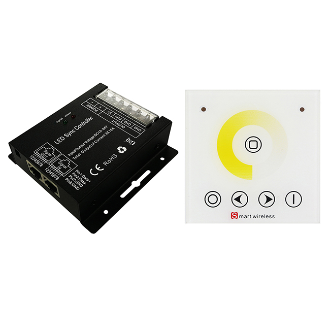
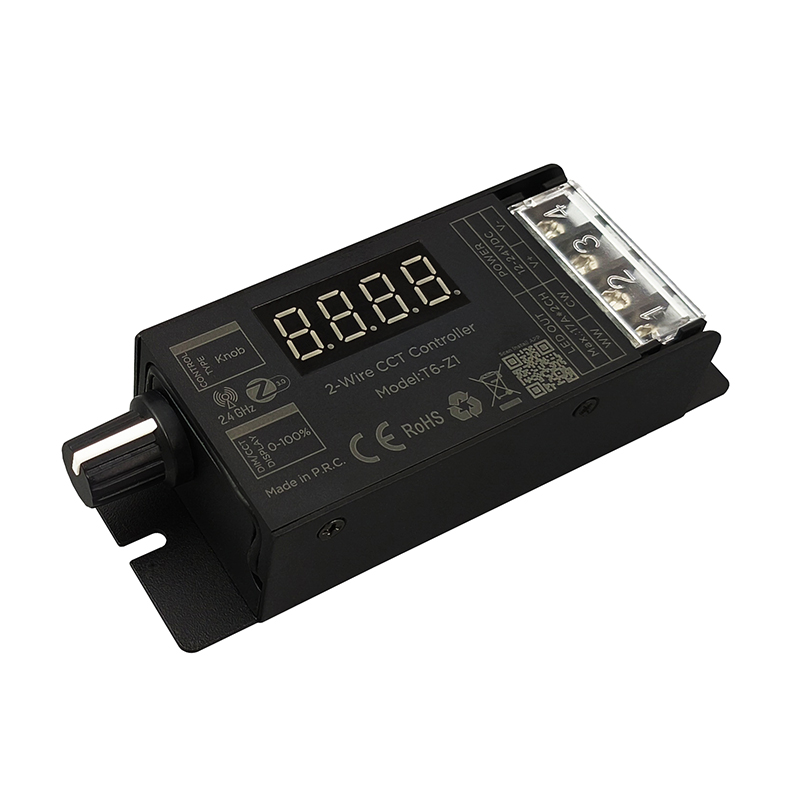
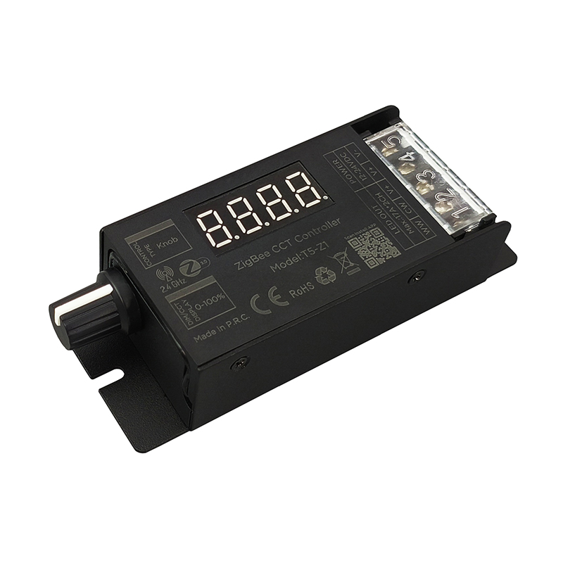
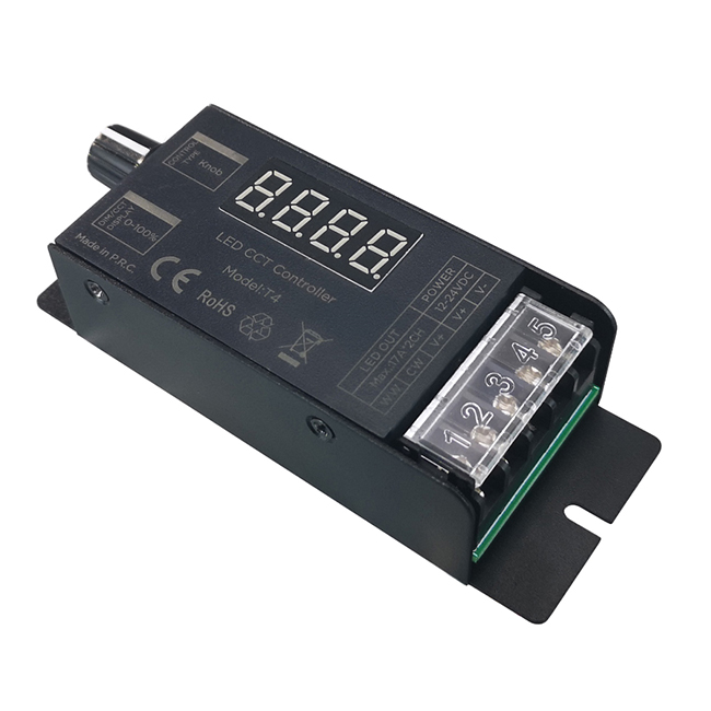
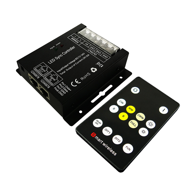
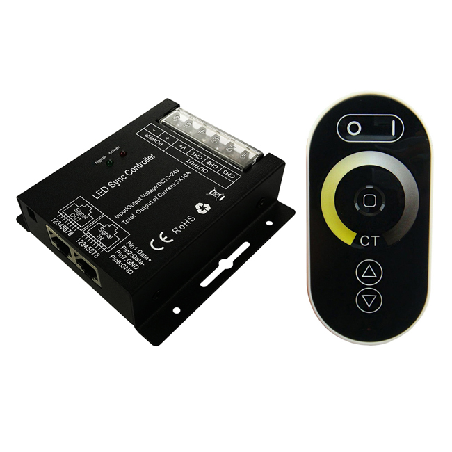
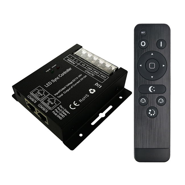
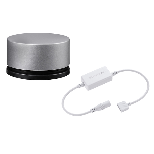
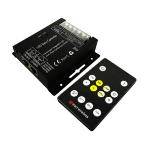
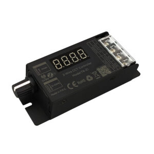
- Designed for CW+WW constant voltage LED lights, Working voltage DC12-24V.
- Two channels output, Max. load current: 2CH*10A; Max. load power: 240W/12V; 480W/24V.
- Adopts full-touch wall panel remote control with fashion appearance, no need line-of-sight. Control range up to 20 meters. The working voltage of wall-panel is AC90-265V.
- Structure/dimension/installation of the wall panel according to the 86-type European standards.
- Memory function, each time power-on reserve the mode which stop in the last power-down.
- Long-press the brightness and speed key can get the fast adjustment, convenient for operation.
- Multiple controllers can work synchronically when connected by network cable through the RJ45 connector, the network cable between 2 ports up to 100 meters.
- Warranty of this product is two years, exclude the artificial situation of damaged or overload working.
Technical Parameters
Controller
| Working temperature | -20-60℃ | Supply voltage | DC12V-24V |
| Static power consumption | <1W | Connecting mode | common anode |
| Grayscale | 256 levels | Speed stage | 100 grade |
| External dimension | L91*W88*H24 mm | Packing size | L102*W102*H66 mm |
| Net weight | 200g | Gross weight | 210g |
| Mode | 7 | Remote distance | Up to 20M |
| RF frequency | 433.92Mhz | Memory function | support |
| Output | 2 channels | Output current | ≤10A(each channel) |
| PWM frequency | 400Hz | Max. Output power | 12V240W, 24V480W |
Remote control
| Ambient temperature | 0-45℃ | Working voltage | AC90-265V(50/60Hz) |
| Standby power | 0.2W | Working power | 2W |
| Net weight | 130g | RF frequency | 433.92MHz |
| Dimension | 86*86*34mm | RF distance | ≤20m |
| Structure | 86-type European standard | ||
Interface Specifications
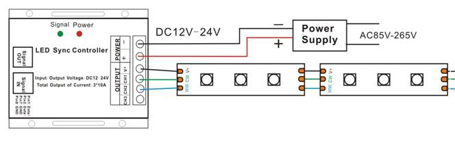
Connection:V+→COM、CH1→CW、CH2→WW、CH3→NC (no connect);
Direction for use
- Connect the load wire at first, followed by the power wire; Please ensure short circuit can not occur between wires before turning on the power;
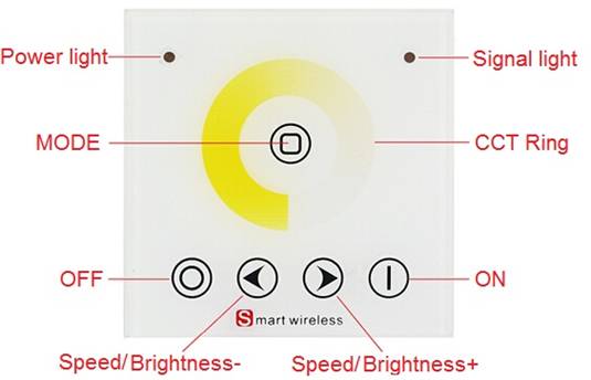
- Adopts RF full touch wall-panel remote control, with one dimming ring and 5 function buttons.
- The signal light flash– represents the signal has been sent well;
The function of buttons are shown as below:
7 modes in total as below:
| NO | Patterns | Remarks |
| 1 | Static WW | Brightness is adjustable |
| 2 | Static CW | |
| 3 | Static CW+WW | |
| 4 | CW and WW flash alternately | Speed is adjustable, brightness is unadjustable |
| 5 | CW and WW fade alternately | |
| 6 | CW and WW flash | |
| 7 | CW and WW fade |
Matching code operation
If unique-control or new-coded-remote is needed, pairing the remote and the receiver as below operation instruction before using:
- Step 1: Pressing key “mode” and hold on, power on the controller, the load LEDs will be 50% brightness white as responding.
- Step 2: Continuously to press the key “ON“ for 3 times within 5 seconds after step 1 ,the brightness of LEDs will change from 25% -10% as responding.
- Code learning successfully, the LEDs will be back to the status before the power off, and the receiver only can be control by the remote.
- If not, please re-operate from step 1 to 2.
Clear code operation
Back to factory default, wall-panel can be controlled by any one the same remote control.
- Step 1: Pressing key “Mode” and hold on, power on the controller, the load LEDs will be 50% brightness white as responding.
- Step 2: Continuously to press “Speed/Brightness –“ 3 times within 5 seconds after step 1 ,the brightness of LEDs will change from 25% -10% as responding.
- Code clearing successfully, the LEDs will be back to the status before the power off, and the receiver can be controlled by any remote control(any one the same remote control can be used to clear the code).
4. If not, please re-operate from step 1 to 2.
Wall-panel Installation instruction
Step 1: Fixing the bottom cover into the wall; Step 2:Fixing the metal frame into the bottom cover
with screws( projecting part upward )
Step 3: Pressing the wall-panel into the metal frame, after connecting well the input and output wires.
Typical Applications
Application Circuit 1: (Tips:CH1→CW,CH2→WW)
Application Circuit 2:( Synchronization function with network Line)
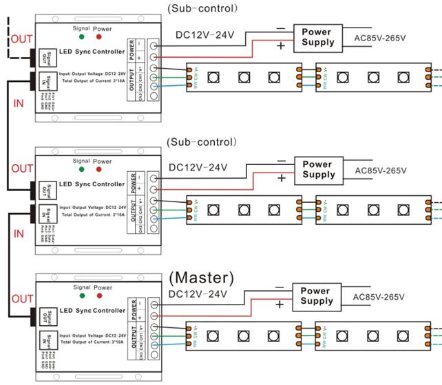
Tips: The green signal indicator light will uniform flash with proper communication, and will off with any incorrect signal connection (like: poor contact, confused input and output, wrong wire order).
Reviews
There are no reviews yet.